Anaconda
Well-Known Member
- Posts
- 5,541
- Location
- Thames Valley
Interesting, mine pass and so do my son's on both his Ninety and D2.If thay are spot lights for MOT thay need to be switched independent
Interesting, mine pass and so do my son's on both his Ninety and D2.If thay are spot lights for MOT thay need to be switched independent
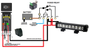
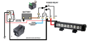
Also for info I have spliced the yellow wire in the images shown above to the H'beam feed <snip>
Maybe he has fitted some relays?If you have done that, wired a Neg to a Live, it's no wonder they don't work ... you have taken the earth away from the LED's and they won't work if you do that.
Also if they are 100W lamps and ther are 2 of them, that's an additional 17Amps that the feed (the one i've asked you about but you haven't replied) has to provide, there is likely to be more than just a headlamp not lighting ... I presume that all that current isn't passing through the column light switch ?
There is a 30 amp fuse between battery and relay. The yellow wire connected to the headlight H'beam feed is a trigger wire that operates the relay once it senses power. It is labelled 'To Negative/H'Beam switch'. I'd imagine this is the wire causing all the problems but apart from to negative where else would it go. There is already a switch built into the harness that arms the spotlights but don't switch them on. They only come on when you use the flasher. If you switch them off using the switch they then don'e operate with the flasher. I'm guessing this is so that you can choose when you want to use them or not.If you have done that, wired a Neg to a Live, it's no wonder they don't work ... you have taken the earth away from the LED's and they won't work if you do that.
Also if they are 100W lamps and ther are 2 of them, that's an additional 17Amps that the feed (the one i've asked you about but you haven't replied) has to provide, there is likely to be more than just a headlamp not lighting ... I presume that all that current isn't passing through the column light switch ?
There is a 30 amp fuse between battery and relay. The yellow wire connected to the headlight H'beam feed is a trigger wire that operates the relay once it senses power. It is labelled 'To Negative/H'Beam switch'. I'd imagine this is the wire causing all the problems but apart from to negative where else would it go.
There is already a switch built into the harness that arms the spotlights but don't switch them on. They only come on when you use the flasher. If you switch them off using the switch they then don'e operate with the flasher. I'm guessing this is so that you can choose when you want to use them or not.
That sounded like the problem to me. I had that challenge putting spotlights on my td5. On more modern vehicles (like the td5) the factory switches are all on the negative side of the circuit. On an earlier defender as the OP has will be on the positive side. It sounds like @_Stingrey_ is trying to use a prebuilt wiring loom that came with the spotlights. This may not be suitable for a vehicle of this age.It gets switched to negative. Modern cars do that, the circuit is live and you connect the negative to complete the circuit.
You, on the other hand, sound like you are switching live (+) although it's difficult to tell as your flow of information isn't...
Are both head lights not on the same fuse??? I have to admit I didn’t look as I presumed that they would be in the same fuse.Have you checked the fuses?
As I said in my first post "Also check fuses, I seem to remember each headlight is fused separately."Are both head lights not on the same fuse??? I have to admit I didn’t look as I presumed that they would be in the same fuse.


Headlights sorted. Thanks Grebby.
How need to sort the spot lights and where that wire labelled 'To Negative/High Beam'?
Once I have identified the correct termination of this wire I feel the spots will also work as they should.
Direct from the battery via a fuse and relay.So @Grebby suggested you check the fuse ... did you find it was blown ?
Did replacing the fuse and disconnecting the "To Negative/High Beam" yellow wire get your headlights working again ?
You don't connect it to the live feed for the headlights high beam (you have discovered) as this blows the fuse ...
Where else have you tried to connect it to and it doesn't work ??
Are we not back at the start here ?
So where is the power (+ 12V) coming from to light up these 'spots' ...?
Direct from the battery via a fuse and relay.
Welcome To LandyZone, the Land Rover Forums!
Here at LandyZone we have plenty of very knowledgable members so if you have any questions about your Land Rover or just want to connect with other Landy owners, you're in the right place.
Registering is free and easy just click here, we hope to see you on the forums soon!