wiring/power connections for the tailgate latch FL2

This site contains affiliate links for which LandyZone may be compensated if you make a purchase.
there would be a tiny printed circuit board holding the motor and possible the latch micro switch in the lock mechanism ,the CEM would be a partial printed circuit board containing the Field effect transistors and relays .
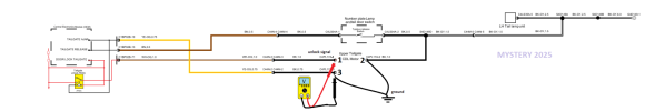
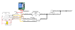
Try running ground from negative terminal of battery to pin 2 and 3 then latch the lock closed press tailgate open on switch and see if you get 12 volt on terminal 1 and that the lock opens . I would also check the loom where it enters the tailgate and the body for damaged or broken cables
Hi again. I will try this maybe not until tomorrow as I have sheep to move around today Please tell me, why is it called a "motor" when surly it is a solenoid? Thanks Ken
 
Hi again.

I have not opened up the CEM but have disconnected the 8 pin connector to the latch. I have measure the resistance across terminal 1 and 2 and for this unit I get 5 ohms. Naturally with the latch closed, I have connected a 12volt supply across terminals 1 and 2 (+ to terminal 1) The latch does not open. I have a 2.5A stable power supply which as you would agree should be enough power for a resistance of 5 ohms. But my power supply registered “over load” so it would seem it could do with more power to operate – your 5 amps again.

I do not have an isolated 5A supply by could take a fused line off the battery – I have a 12V supply on the left had side of the back door (I assume that all Fl2 do!) but do not know what the fuse rating of this is off hand?

I am thinking that, as both the old and the new latch do not open when supplied with 12volts, that the 3rd wire need to be involved?

The pins on the latch are very close together so it is difficult to play around with the terminal. Do you know the type of connector used on this – if so I could order one on Ebay.
 
I'm not sure if the motor is controlled by PWM (pulse width modulation) if so this would put the control voltage signal at 5volt halfwave but going by the diagram i would say this is not the case . so with the motor disconnected ground the terminals 2 and 3(this will eliminate a faulty lock micro switch ) and actuate the tailgate via the remote or open button on the tailgate whilst measuring the voltage on terminal 3
 

Attachments

  • fl2 DOOR LOCKS 2 - Copy - Copy - Copy.png
    fl2 DOOR LOCKS 2 - Copy - Copy - Copy.png
    63.7 KB · Views: 16
Thank you for your patience with me I have been juggling a number of balls as well as this tailgate problem.
I popped back to the garage this morning Saturday as I know the guy's there and they showed me that injecting 12 volts on to terminal one with the connector (connected to the latch) resulted in the latch opening. If does not open when the connect is disconnected, which i what i have been trying on both latches. So I guess that comes back to your statement about Pin 71 and the need to get 12 volts on that wire. I hope to have a look tomorrow as it been raining most of the day.
Bye
 
is that not the Electric parking brake module ? have you checked the cables in the corrugated rubber sleeve that links the body to the tail gate for broken wires before condemning the ECU you could have a broken wire
take a look at link shows the CJB https://www.freel2.com/forum/post447906.html
Hi Again, maybe it is the parking brake moule BUT that is what/where the garage boys told me the "eletronic control unit" was that they felt had gone wrong!!!

Where is it to be found - sorry I do not know.

have looked for broken wires in the rubber sleeve at the top left hand side of the tail gate and can not see any problems - there are no marks or cuts on the wiring loom.

If you could point out the locatio of the ECU or BCM - whatever the correct name is. Thanks and regards
Ken
 
try
 

Attachments

  • FREELANDER 2007 - 2011 WORKSHOP MANUAL-1737.png
    FREELANDER 2007 - 2011 WORKSHOP MANUAL-1737.png
    1.1 MB · Views: 11
  • FREELANDER 2007 - 2011 WORKSHOP MANUAL-2001.png
    FREELANDER 2007 - 2011 WORKSHOP MANUAL-2001.png
    840 KB · Views: 12
Hi again Mystery,

Okay, thanks for that info. I think I have come to the end of this journey. Looking st your two pages from the manual I feel there is little I can do to address this problem. If I do remove the glove compartment and get access to the CJB I have no test equipment to access any data other than an AVO. I do thank you again for your time and patience with me and wish you all the best. Ken
 
I personally would not give up if only to prove that the problem is the CJB and would check pin 72 ,you would only have to remove the glove box to locate the white /orange cable and using a pin gently inserted through insulation to check for 12 volt signal without removing the CJB the entry point then taped up .not sure if you located the connector C44 N to check for corrosion etc i do not have a copy of the connection diagrams so its location unknown could be in rear side panels ? as to the AVO a good accurate test instrument i still have my AVO-MK8.
if the problem is in the CJB it can be over come by fitting a remote relay such as https://www.ebay.co.uk/itm/33612650...fFiOXbwNqGuNF52AAAAAA&loc_physical_ms=9208479
Okay thank you for your positive words. Sorry I did not know where the CJB was - the last place I would have assumed was behind the glove box, but I will try to have a look behind the glove box over the next day or so - noe the rain has stopped I have a few jobs to do..

Funny you suggested the wireless remote relay. That is what had intended to use BUT connected to 12volts via the 12V cig socket on the left hand side of the tail gate. For info I put 12volts onto pin one today and the latch opened without problems so if I cannot get into the CJB I will frig an opening system around that 12V supply.

I need to read ALL your comments a fresh.

Not splitting hairs, I notice the workshop manual is 2007 to 2011 but I am sure you would agree thinks will not have changed.

I do have a AVO 8 but tend to use a DVM these days – Chauvin Arnoux kit

Will keep you informed.

Bye Ken
 
not knowing your vehicle spec but there is a AUX fuse box fitted to the rear of the vehicle that power the cigar lighter trailer socket etc you could use the trailer accessory feed to power the new relay C4BRO2B-13 if this is not in use.
not knowing your skill set but you could attach a new cable and pin to either C4BRO2B-15 OR -16 and insert new fuse i would think the AUX fuse box would be located behind the side trim or like the BRAKE module in the floor (the diagram are viewed better if opened in MS Paint)
 

Attachments

  • fl2 AUX FUSE BOX.png
    fl2 AUX FUSE BOX.png
    264.6 KB · Views: 8
  • FREELANDER 2007 - 2011 WORKSHOP MANUAL-1563.png
    FREELANDER 2007 - 2011 WORKSHOP MANUAL-1563.png
    550.4 KB · Views: 10
  • FREELANDER 2007 - 2011FUSE BOX'S.png
    FREELANDER 2007 - 2011FUSE BOX'S.png
    1.2 MB · Views: 11
  • fl2 DOOR LOCK REMOTE RELAY.png
    fl2 DOOR LOCK REMOTE RELAY.png
    119.6 KB · Views: 11
you for your positive words. Sorry I did not know where the CJB was - the last place I would have assumed was behind the glove box, but I will try to have a look behind the glove box over the next day or so - noe the rain has stopped I have a few jobs to do..

Funny you suggested the wireless remote relay. That is what had intended to use BUT connected to 12volts via the 12V cig socket on the left hand side of the tail gate. For info I put 12volts onto pin one today and the latch opened without problems so if I cannot get into the CJB I will frig an opening system around that 12V supply.

I need to read ALL your comments a fresh.

Not splitting hairs, I notice the workshop manual is 2007 to 2011 but I am sure you would agree thinks will not have changed.

I do have a AVO 8 but tend to use a DVM these days – Chauvin Arnoux kit

Will keep you informed.

Bye Ken
The CJB is definitely behind the glove box, as it's close to the fuse box, also down there.
The module in the boot is for the electronic parking brake, and not relevant for this issue.

As above, test the output on the orange/white for a DC pulse to unlock the boot. It's only short, about 1 second, and is very close to normal battery voltage.

If the pulse is absent, then it's very likely the relay in the CJB is faulty, but it's unusual. If there is a pulse, then the issue is in the wiring between the CJB and lock assembly. I've come across damaged wiring in the flexible trunking between the body and boot on 2 occasions, so that is the most likely place for there to be a problem.

If it is the CJB at fault, then you can pick a permanent live at the rear fuse box, as there are a couple there. Unfortunately the boot power socket is on the accessory supply, so times out after a few minutes of engine off.
 
not knowing your vehicle spec but there is a AUX fuse box fitted to the rear of the vehicle that power the cigar lighter trailer socket etc you could use the trailer accessory feed to power the new relay C4BRO2B-13 if this is not in use.
not knowing your skill set but you could attach a new cable and pin to either C4BRO2B-15 OR -16 and insert new fuse i would think the AUX fuse box would be located behind the side trim or like the BRAKE module in the floor (the diagram are viewed better if opened in MS Paint)
Hi Mr Mystery,

(Sorry the formating as gone up lid.jpg
aux box.jpg
lid.jpg
the wall)

Again thanks for your reply and help. I have decided (right or wrong) to insert a wireless relay into the boot area and drive the latch. However:

I am going to use the 12V cigar lighter as the supply BUT looking at the fuse box at the back cannot seem to find the fuse for this. (yes, I know I can pull each out in turn but) If/when I find it – if it is even in the Aux Fuse Box? I had intended to put a Piggy Back Car Fuse Holder in that fuse slot and take my 12V from there.

My problem is not knowing the location and how to get to your “C4BRO2B-15 OR -16”

Removing F1 and F2 do not cut power to the Cigar lighter but the manual would suggest it should!!. Apart from pulling each fuse out do you have the number?

I have ordered a wireless relay at 433MHz – I know the fob frequency is the same but I was thinking I could/maybe use the fob to operate it. I will test this out on the bench before thinking of installing it in the car. I will keep you informed if I may

A few photos

Bye for now Ken

 
could do with image of aux fuse box showing what vacant fuse holders and relay have connections fitted
 

Attachments

  • lid.jpg
    lid.jpg
    317.6 KB · Views: 5
Back
Top