Hi everyone - looking at a friend's 2006 4.4 V8 Vogue RR which has just started going straight into limp mode (2200rpm max) from startup. iCarsoft CR MAX shows P0102-00 MAF low input and P0121 Throttle pedal position sensor A circuit range performance. Also the Live Data display shows a constant 0v on the MAF output (presumably going back to the ECM?). I have cleaned the MAF, replaced throttle body and removed and tested the throttle pedal assembly on the bench with an external 5v - all good and no change.
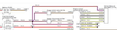
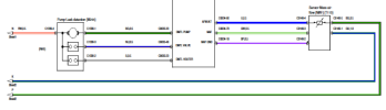
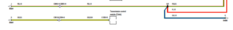
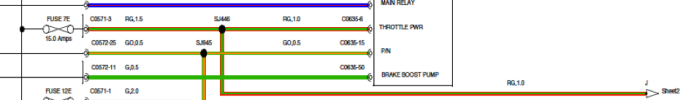
My question is - is the actual MAF fed with both 5v and 12v? The description in RAVE infers that it is and the wiring diagrams show that it should be also. However, I am not getting the 12v feed on the 5 pin plug that plugs into the MAF - only 5v and three grounds. There are 5 wires which again corresponds with the wiring diagram. It looks as if the 12v comes from a fuse and is shared with other devices.
All I really need to know (to be able to continue this train of investigation) is does this particular setup require the 12v and if it wasn't there, could that be my problem. If anyone had the same vehicle, it would be great if they could confirm that there is 12v on pin 1 and 5v on pin 5 with the ignition on and the MAF unplugged.
Many thanks all....Peter