Hi guys, can any one please post some info about the pinout of the 3 pin height sensors?? I know they hall effect sensor and tracking what should go where is a bit pain.
Could you please give diagram etc.
the info i have so far is that:
Pin1 - earth
Pin4 - signal
Pin5 - power.
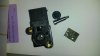
however, i stripped one apart and for me looks like pin 5 should be ground as its connected to the pcb plan. but i don`t want to take all 4 apart to confirm that they are the same.
Also are the 5V or 12V sensors??
Thanks for any help
Could you please give diagram etc.
the info i have so far is that:
Pin1 - earth
Pin4 - signal
Pin5 - power.
however, i stripped one apart and for me looks like pin 5 should be ground as its connected to the pcb plan. but i don`t want to take all 4 apart to confirm that they are the same.
Also are the 5V or 12V sensors??
Thanks for any help
Attachments
Last edited:
") )
)