D2 towbar electrics

This site contains affiliate links for which LandyZone may be compensated if you make a purchase.
And I read the instruction's and those from @sierrafery . Admittedly they are not the best, but if you have it in hand and the car in front of you, it should be a bit self explanatory.
What split charge?
I think you are confusing yourself.

I am struggling.
Fit it as stated for a 13pin and the caravan/horsebox should match?

J
To be exactly, I have no idea of where the relay is connected to, the instruction points to somewhere under the passenger seat, I don't think that is correct. The 13-pin socket is going to be connected to caravan.
 
Right you should not get clearer than this

Take a feed from the Battery via a 30A Fuse to Pin 9 on the Trailer Socket in 2.5mm Cable (Permanent Supply)

Using a standard automotive relay rated at 40A
Take a feed from the Battery via a 30A Fuse to Pin 30 on the Relay in 2.5mm Cable (Permanent Supply)
Take a feed from the Relay Pin 87 to Pin 10 on the Trailer Socket in 2.5mm Cable (Switched Supply)

Take a feed from the W wire on your alternator to Pin 86 on the relay
Take a wire from Pin 85 on the relay to earth / ground
(Alternively use a voltage sensative relay)

Ideally cables running under the vehicle will be sleved / in conduit
Thank you for your solution Andy. There are two issues, Firstly, 30A to pin 30 might not be enough to deal with surge current for leisure batter/fridge on start. Secondly, the alternator is connected with the battery and has permanent power, the relay would still draw current on standby, the battery would run flat. As I looked at STC50179 as said previously, LR wiring solution seems better, the pin 30 is connected to the battery +terminal and the pin 86 to WG ignition, the relay is energized on ignition.
 
30A will be sufficent

I said to use the W wire on the alternator - I suggest you google this to find how it works
 
30A will be sufficent

I said to use the W wire on the alternator - I suggest you google this to find how it works
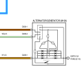
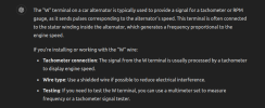
do you mean WG wire on D2 alternator? W wire provides a pulse signal, but the pin 86 must have constant high voltage e.g. >13.4v to keep the relay closed. In LR wiring, the relay is not closed until the engine starts. Screenshot from 2024-10-11 12-18-39.pngScreenshot from 2024-10-11 12-17-39.png
 
So the way the alternator "Red" light on the dash works (WG Wire)
When you turn the igition on 12V is feed to the Alternator which earths this feed - Red Light On on dash
When the alternator satrts charging it puts 12V on this cable turning off the red light on the dash as it now has 12V on either side of the bulb (No Potential difference)

If you connect a relay coil into this circuit
When you turn the igition on 12V is feed to the Alternator which earths this feed but has a far lower resistance than the rely coil so the relay will not turn on
When the alternator starts charging it puts 12V on this cable which will then turn the relay on and dash light off
 
So the way the alternator "Red" light on the dash works (WG Wire)
When you turn the igition on 12V is feed to the Alternator which earths this feed - Red Light On on dash
When the alternator satrts charging it puts 12V on this cable turning off the red light on the dash as it now has 12V on either side of the bulb (No Potential difference)
The WG wire has nothing to do with the red light, the warning light works with the NY wire the way you explained just that it has power through the IP from F27. The WG wire is from F24 as i explained before, the so called "exciter wire".

1728747356888.png
 
Back
Top