Am doing the track repair today.
Need to find the value of RW1 & RW2!
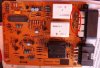
Now have a full BoM. Got to work out circuit of ECU.
Need to find the value of RW1 & RW2!
Now have a full BoM. Got to work out circuit of ECU.


cowasaki
Well-Known Member
I'll have a look if mine had them and dig the box out. I didn't bother with an ECU when I wired my windows up I just wired them via the switches which is absolutely fine.
Take the 5 pin connector and feed 12v into the centre pin, ground into 2 & 4 then 1 & 5 go to the motor (if it goes up when you press down and vice versa just swap them round!)

The motors pull an acceptable current to not require relays but if you want a relay you could add them.
Take the 5 pin connector and feed 12v into the centre pin, ground into 2 & 4 then 1 & 5 go to the motor (if it goes up when you press down and vice versa just swap them round!)
The motors pull an acceptable current to not require relays but if you want a relay you could add them.
I might give that a try, via a fuse as a circuit check. But I want to fix these bloody things.
Might make up a "Simple ECU" using your circuit and a new PCB. Connecting up to existing wiring looms.
Might make up a "Simple ECU" using your circuit and a new PCB. Connecting up to existing wiring looms.
its behind the passenger glove box
That's the one ��
Look on the reverse for dry joints.
Have yu read this thread?
Am bidding on one on eBay, but if it's cheap, would be useful as a spare. Pm me how much.
")
Done. Pm me yo PayPal info. I will send yu a gift.
cowasaki
Well-Known Member
Done. Pm me yo PayPal info. I will send yu a gift.
Will do. anything else you want off it? It's only there for the Defender bits!
cowasaki
Well-Known Member
The window lift bit was part of tutorial 1 (NOTE THE DISCO1 BIT AT THE END)....
Electric window motors are just normal motors so if we connect them to 12v they go one way and if we swap the connections around the motor rotates in the other direction and the window goes the other way.
The normal way to connect an electric window motor is to wire it using the universal 5 pin window switch
The connections of these standard window switches is as follows:

So you can see that when nothing is pressed both sides of the motor get GND and nothing happens. When DOWN is pressed 12v from pin 3 goes to pin 5 and the motor rotates sending the window down whilst when UP is pressed 12v from pin 3 goes to pin 1 instead and the motor rotates the other way sending the window up. I am showing this with the supply connected to the battery via a fuse and during these tutorials I will do that just to show it’s getting 12v but in reality I would connect it to IGNITION LIVE which is the 12v power connection when the key is turned to ON.
There are alternative wiring diagrams using different switches.
Universal illuminated 7 pin switch
This will be as above with the 2 extra pins for the light. Connect as per suppliers instructions although this will normally be on connection to ground and the other to the side light on OR ignition on circuit depending on how you want them to light.
Universal illuminated 6 pin switch
This is as per the 7 pin switch but with this switch the ground connections are fixed so it takes ground from there and the 6th pin is connected to side light or ignition
Discovery pre D1s 1995
as per 5 pin universal switch.
Discovery D1s 1995 onward 6 pin switch
These are a great option for defenders as the switch is virtually the same size as the emergency light/ rear heater switch. For this one there are three options depending on how you are connecting it:
(A) if you are connecting it into a discovery D1s 1995 onwards OR using a discovery window ECU then follow the following wiring - 1 = out A, 2 = out B, 3 = supply from window ECU, 4 = ground, 5 = supply from window ECU & 6 = illumination
(B) if you are using it to replace a universal switch AND NOT using a roll up interface then you need to connect it as follows: 1 = out A, 2 = out B, 3 = ignition live, 4 = ground, 5 = Ignition live & 6 = illumination
(C) if you are using it to replace a universal switch AND using a roll up interface then you need to connect it as follows: 1 = out A, 2 = out B, 3 = ground, 4 = ignition live, 5 = ground & 6 = illumination/ground. This will work fine and the switch will illuminate as soon as the ignition comes on. If you want to illuminate it by the side lights then you need to connect the side light live to a relay as follows: 85 – side light live, 86 & 30 ground & 87 – switch pin 6.
I will talk about roll up interfaces when I talk about alarms in a later article.
Electric window motors are just normal motors so if we connect them to 12v they go one way and if we swap the connections around the motor rotates in the other direction and the window goes the other way.
The normal way to connect an electric window motor is to wire it using the universal 5 pin window switch
The connections of these standard window switches is as follows:
So you can see that when nothing is pressed both sides of the motor get GND and nothing happens. When DOWN is pressed 12v from pin 3 goes to pin 5 and the motor rotates sending the window down whilst when UP is pressed 12v from pin 3 goes to pin 1 instead and the motor rotates the other way sending the window up. I am showing this with the supply connected to the battery via a fuse and during these tutorials I will do that just to show it’s getting 12v but in reality I would connect it to IGNITION LIVE which is the 12v power connection when the key is turned to ON.
There are alternative wiring diagrams using different switches.
Universal illuminated 7 pin switch
This will be as above with the 2 extra pins for the light. Connect as per suppliers instructions although this will normally be on connection to ground and the other to the side light on OR ignition on circuit depending on how you want them to light.
Universal illuminated 6 pin switch
This is as per the 7 pin switch but with this switch the ground connections are fixed so it takes ground from there and the 6th pin is connected to side light or ignition
Discovery pre D1s 1995
as per 5 pin universal switch.
Discovery D1s 1995 onward 6 pin switch
These are a great option for defenders as the switch is virtually the same size as the emergency light/ rear heater switch. For this one there are three options depending on how you are connecting it:
(A) if you are connecting it into a discovery D1s 1995 onwards OR using a discovery window ECU then follow the following wiring - 1 = out A, 2 = out B, 3 = supply from window ECU, 4 = ground, 5 = supply from window ECU & 6 = illumination
(B) if you are using it to replace a universal switch AND NOT using a roll up interface then you need to connect it as follows: 1 = out A, 2 = out B, 3 = ignition live, 4 = ground, 5 = Ignition live & 6 = illumination
(C) if you are using it to replace a universal switch AND using a roll up interface then you need to connect it as follows: 1 = out A, 2 = out B, 3 = ground, 4 = ignition live, 5 = ground & 6 = illumination/ground. This will work fine and the switch will illuminate as soon as the ignition comes on. If you want to illuminate it by the side lights then you need to connect the side light live to a relay as follows: 85 – side light live, 86 & 30 ground & 87 – switch pin 6.
I will talk about roll up interfaces when I talk about alarms in a later article.