Dynamic Antiroll error

This site contains affiliate links for which LandyZone may be compensated if you make a purchase.

alfapat

Active Member
Posts
210
Location
Elgin
So , I linked to a thread on the wrong forum , so on here with a code on RR Sport dynamic roll.

Code is C1B11-1D(AF) this off a GAP IID Tool. Im told in the last forum that this is nothing to do with the pressure transducer . This is the path I am following at the moment. .
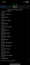
I need to go into live data on the dynamic roll ecu .
Any ideas on something else that I read. that if I join the links on the relay , I will get some data. Help required please.
 
IMG_1223.pngThe choice I want of this group of ecu’s doesn’t seem to be there.
 
Code is C1B11-1D(AF) this off a GAP IID Tool.
according to the DTC index for the RRS dynamic response module the problem is with the pressure controll valve

1710092723933.png


the pressure control valve's solenoid is on the left side of the block nr 17 in the pic below, unplug it and measure it's resistance with multimeter, it should have around 5.7 Ohm, if you can't reach the pins in situ undo the nut(cap) and remove it if that resistance is good it can be a wiring issue on that circuit ... would be good if that GAP tool could run circuit output test like nanocom can for the D2 ACE cos then you could see if the solenoid is cliking or not on command otherwise a continuity test on that circuit is needed and if the circuit is OK too then the ECU is suspect or it can be a mechanical failure of the valve in the block(nr 19), let's hope that the solenoid is dead cos then it's not a hard job ... good luck

1710093506835.png
 
according to the DTC index for the RRS dynamic response module the problem is with the pressure controll valve

View attachment 312361

the pressure control valve's solenoid is on the left side of the block nr 17 in the pic below, unplug it and measure it's resistance with multimeter, it should have around 5.7 Ohm, if you can't reach the pins in situ undo the nut(cap) and remove it if that resistance is good it can be a wiring issue on that circuit ... would be good if that GAP tool could run circuit output test like nanocom can for the D2 ACE cos then you could see if the solenoid is cliking or not on command otherwise a continuity test on that circuit is needed and if the circuit is OK too then the ECU is suspect or it can be a mechanical failure of the valve in the block(nr 19), let's hope that the solenoid is dead cos then it's not a hard job ... good luck

View attachment 312364
Ok , many thanks I have a spare pressure control valve so will measure that first. I have in fact measured a voltage off the plug off two pins but I'll check that tomorrow. I was originally going to change that and so a guy who is very knowledgeable and runs a L/R garage said that its rare for a PCV to go so I dismissed this , and centred in on pressure sensor . Back to original thought then!
Meanwhile I will email GAP to find out if there should be live values on the Active roll ECU. Updating first of course otherwise I might be wasting there time .
 
Meanwhile I will email GAP to find out if there should be live values on the Active roll ECU
It's possible to not be able to do that cos it seems that for the RRS nanocom can't do that either even though it can for the D2, what year is your vehicle ? is it L320, L494 or L460?
 
It's possible to not be able to do that cos it seems that for the RRS nanocom can't do that either even though it can for the D2, what year is your vehicle ? is it L320, L494 or L460?
L320 . 08 plate. Reading the manual for GAP it does say on page 106 that it’s all possible to read live values . I’ve just updated the tool so will see if it’s enabled the ecu list .
Measured the resistance on the Pressure control valve ant comes 5ohms and I measured my spare one snit 4.9 .
I still can’t see the live value of the Dynamic roll ecu .

Looking at the wiring diagram I have there is a junction /connection on the loom from the PCV to the module , so a bit of puzzle to find . I can also pick up the voltage again at the plug to verify voltage and earth qualities . Although I am sure I have done this .

I also got an email back from GAP saying that they provide the same list LR does with their official diagnostic tool. BUT, unsure about this specific one .

Update, I have just got an email granting me access to the ACTIVE ROLL ECU , so just a question of installing into GAP tool .

we are getting somewhere hopefully.
 
Last edited:
L320 . 08 plate. Reading the manual for GAP it does say on page 106 that it’s all possible to read live values . I’ve just updated the tool so will see if it’s enabled the ecu list .
Measured the resistance on the Pressure control valve ant comes 5ohms and I measured my spare one snit 4.9 .
I still can’t see the live value of the Dynamic roll ecu .

Looking at the wiring diagram I have there is a junction /connection on the loom from the PCV to the module , so a bit of puzzle to find . I can also pick up the voltage again at the plug to verify voltage and earth qualities . Although I am sure I have done this .

I also got an email back from GAP saying that they provide the same list LR does with their official diagnostic tool. BUT, unsure about this specific one .

Update, I have just got an email granting me access to the ACTIVE ROLL ECU , so just a question of installing into GAP tool .

we are getting somewhere hopefully.
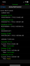
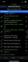
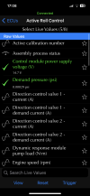
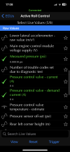
So now I have the Active Roll EcU and scrolling down the various components and values therein . I get this —with engine running and fault light on . IMG_1237.pngIMG_1236.pngIMG_1235.pngAny interpretation would be helpful , but it still looks like a wiring fault , there is good voltage to ecu module .
 
Last edited:
I cheked the diagram and it's not like on the D2 as on the D2 when the warning is on the ignition feed to the ECU is disabled cos the ACE relay is open albeit the ECU has the main battery feed as well... on the RRS i presume that being on default mode is the same principle just that it doesnt have an external ACE relay so everything is managed by the ECU and unfortunately this way you can't force power into the system(on the D2 the relay is removed and bridged to see live inputs with warning on otherwise they are all 0) so that 0 reading on the PCV might not be relevant. Try that "trigger" command on the PCV see if it clicks or not and check that with a DCV too cos if that function is to test the circuit the DCV should click i presume. As the PCV solenoid checks out with 5 Ohm on your's to check the circuit unplug C0647 and measure across pins 1- 2(purple - black/green wires) cos if the circuit is good you should get very close to that 5 Ohm there

1710357550493.png
 
Last edited:
I cheked the diagram and it's not like on the D2 as on the D2 when the warning is on the ignition feed to the ECU is disabled cos the ACE relay is open albeit the ECU has the main battery feed as well... on the RRS i presume that being on default mode is the same principle just that it doesnt have an external ACE relay so everything is managed by the ECU and unfortunately this way you can't force power into the system(on the D2 the relay is removed and bridged to see live inputs with warning on otherwise they are all 0) so that 0 reading on the PCV might not be relevant. Try that "trigger" command on the PCV see if it clicks or not and check that with a DCV too cos if that function is to test the circuit the DCV should click i presume. As the PCV solenoid checks out with 5 Ohm on your's to check the circuit unplug C0647 and measure across pins 1- 2(purple - black/green wires) cos if the circuit is good you should get very close to that 5 Ohm there

View attachment 312585
Ok , that’s great , I think I get your help with that , I will try this on Friday pm , as I’m off then . Thank you so much for replying , much appreciated .
Looking at the wiring diagram and when you say to measure at C0647 , would it be better measuring at C0771 as that would be the end feed at the pcv plug .

To add I get what you’re saying about testing at your junction, this would ensure that that output at the module would assure the signal is correct . Hopefully I can find the module to measure if this where you want me to do this , where and how accessible is the ARoll module .

Right I have read your guidance once again and missed your diagram of the module and the reference to C0647, now I get what your testing for . On the wiring diagram , I notice there could be a midway connection as well .
 
Last edited:
Right I have read your guidance once again and missed your diagram of the module and the reference to C0647, now I get what your testing for . On the wiring diagram , I notice there could be a midway connection as well .

Yes, read carefully my replies cos i concentrate to be as clear as possible.... there is that C2396 too but you'll have to check there only if it's no continuity or it's too big resistance to the solenoid at the ECU plug according to the fault code, maybe you are lucky to be an interruption there cos seems that can be exposed to water ingress in that position... if you get close to 5 Ohm at C0647 then the ECU becomes suspect, on the D2 the solenoid drivers in the ACE ECU are quite weak and fail, not uncommon but i have no experience with RRS

1710427614626.png
 
Last edited:
Many Thanks Sierra, thats great , I will try harder and concentrate lol !
Will look at this tomorrow.
 
Yes, read carefully my replies cos i concentrate to be as clear as possible.... there is that C2396 too but you'll have to check there only if it's no continuity or it's too big resistance to the solenoid at the ECU plug according to the fault code, maybe you are lucky to be an interruption there cos seems that can be exposed to water ingress in that position... if you get close to 5 Ohm at C0647 then the ECU becomes suspect, on the D2 the solenoid drivers in the ACE ECU are quite weak and fail, not uncommon but i have no experience with RRS

View attachment 312628
Measured at green plug C0647 and the purple -green/black is measuring 1.4 ohms, tried at the back and front of pins .
So not sure what that means .
Also tried to use the trigger but not sure if that works or indeed I know how to to be honest .
 
Measured at green plug C0647 and the purple -green/black is measuring 1.4 ohms, tried at the back and front of pins .
So not sure what that means .
Also tried to use the trigger but not sure if that works or indeed I know how to to be honest .
check the plug's pin disposals in the pic i posted, are you sure you measured across pins 1 - 2(first and second pins from left cavity side) with connector unplugged? pin 1 should be black/green not green/black according to the diagram, it's not the same thing(first is the main colour/second the trace on the wire)...if you measured well and the solenoid checks out with 5 Ohm as you said while you get 1.4 at the C0647 there is a wiring issue on that circuit, check at C2396 cos it might be corrosion in that but at least you found the problem and in the worst case you can rewire that path
 
Back
Top