Discovery Flashers

This site contains affiliate links for which LandyZone may be compensated if you make a purchase.

SteveG4TRA

Active Member
Posts
210
I am interested to find out more about the Discovery S2 (2003) indicator system. Recently in the very cold weather the flashers played up, neither side wanting to start, then flashing very slowly even though the car was started and running. Eventually they came up to normal speed as the car warmed up. Obviously something being effected by the cold I guess.
I suspect the IDM (Indicator Delay Module?) on the Fuse Box Passenger Compartment P101. Why Land Rover couldn't fit a normal standard plug in flasher unit I don't know. So where is the IDM on the Fuse Box. Is it at the back? Is in moulded inside? Can it be replaced? Is it plug in? How does it work?
Any thoughts from the auto-electrical guys out there?
 

Attachments

  • Screenshot_2.jpg
    Screenshot_2.jpg
    32.4 KB · Views: 70
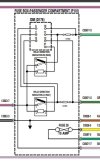
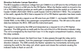
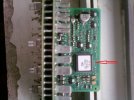
Hi, first of all IDM means "Intelligent driver module", described in the WSM, it's actually the whole unit which is much more than a fusebox and has an integrated circuit soldered into the pcb which has many more functions beside the indicators, these fusboxes(IDMs) are common failure and the easy fix is to replace them with known good one, you need one removed from a facelift, all you have to do is to disconenct the battery first then after the swap and battery reconnection follow what's in the description with the 5 min delay... if this was ruled the next suspect is the BCU which is not plug and play, it needs complex programming with nanocom or similar. yes the indicator's operation was overcomplicated by LR but that's it... see attachments

aamof you can find all the info you need in the wsm and electrical library from RAVE but you need plenty of time...took me about 10 years to know them all by heart o_O
 

Attachments

  • 1706468052765.png
    1706468052765.png
    60.5 KB · Views: 80
  • 1706468131389.png
    1706468131389.png
    126.1 KB · Views: 77
  • 1706468327685.jpeg
    1706468327685.jpeg
    268.8 KB · Views: 75
Last edited:
Hi, first of all IDM means "Intelligent driver module", described in the WSM, it's actually the whole unit which is much more than a fusebox and has an integrated circuit soldered into the pcb which has many more functions beside the indicators, these fusboxes(IDMs) are common failure and the easy fix is to replace them with known good one, you need one removed from a facelift, all you have to do is to disconenct the battery first then after the swap and battery reconnection follow what's in the description with the 5 min delay... if this was ruled the next suspect is the BCU which is not plug and play, it needs complex programming with nanocom or similar. yes the indicator's operation was overcomplicated by LR but that's it... see attachments

aamof you can find all the info you need in the wsm and electrical library from RAVE but you need plenty of time...took me about 10 years to know them all by heart o_O
HI SF
Thanks for the description and pictures which makes sense.
I thought there would be a PCB inside the Fuse Box Passenger Compartment P101 even though I have never seen inside one. There are some six Siemens and NEC automotive dual PCB mounted relays shown in pictures of it, so it was going to be a complicated unit.
I guess the giveaway is that the indicators are operated from the stalk via the BCU over SK5 part of the cars Serial Data Bus. The IC shown in the piggy back sub-PCB is obviously the Serial Data Bus decoder for all the devices fused and operated from this Fuse Box, such as the windows, fan, AC, fog lights etc and of course the indicators. My guess is somewhere on the main PCB will be the electronic flasher circuit (triggered from the Serial Data Bus IC) plus two 1 ohm current detection resistors to speed up the flasher when a bulb blows.
I am fairly sure that the fault I describe will be in the IDM not BCU and it will revolve around the flasher active device.
As you say the easy way out if it happens again would be to replace the unit, there seem to be plenty available from the various scrappies.
 
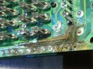
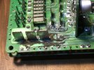
Sort of... you can try to open the unit, insert coins all around at the clips then you can take the covers off, here are examples of what can happen inside... though i've seen cases when nothing was visible while the IDM caused all king of trouble
 

Attachments

  • 1706476730429.jpeg
    1706476730429.jpeg
    568.3 KB · Views: 73
  • 1706476761417.jpeg
    1706476761417.jpeg
    355.5 KB · Views: 74
Yes, that's certainly a couple of cases of water ingress. Whilst the main 12v electrics PCB tracks are fairly heavy duty by nature of the current they have to carry and can be cleaned and repaired in some case, the IDM piggy back PCB tracks are much finer and more fragile.
Without a circuit diagram of the IDM it is difficult for me to know the indicator components. If I felt inclined I could go round the PCB components with a freezer spray until the indicators stop again to identify the culprit but of course in the eyes of Land Rover one was not expected to fault find to component level within the IDM assembly, just replace the whole damn fuse box.
 
Back
Top