Dead Glow Plugs - help!

This site contains affiliate links for which LandyZone may be compensated if you make a purchase.

Chapgrill

New Member
Posts
16
Location
Oxfordshire
Got a 1980 Series III Diesel, with inoperative glowplugs (no dashboard warning light, can't start in cold weather). Seems like an open circuit. Any ideas how I test the circuit and at what points? NB the feed to the plugs goes via a plate on the bulkhead that looks like it isn't insulated - can't find a pic in Haynes to confirm if this is correct or if it's been modified.
chapgrill
 
Is this a 2.25 diesel?

If so, then the glow plugs are connected
1. through a ballast resister (a coil of wire) on the bulkhead in the engine bay
and
2. they are connected in SERIES.

If ONE plug fails, NONE of them work

Test 1 is a simple one, to make sure the wire leading from the bulkhead to the first plug goes live. If it does, test the plugs in situ. One of them will probably test open circuit.

If it doesn't, don't waste time doing anything else till you can get that cable live when it should be.

CharlesY
 
Many thanks - will try your approach when it's light enough to see! Got a feeling the ballast resister may be missing but will check
chapgrill
 
Many thanks - will try your approach when it's light enough to see! Got a feeling the ballast resister may be missing but will check
chapgrill

The ballast resistor is not really essential. It is used so that a warning lamp in the dash glows when the GLOW is supposed to be live. It is very unlikely the resistor is faulty, but it could have lousy connections.

The coil of wire is about an inch in diameter and maybe two inches long. It may be in a small metal box on the bulkhead.

You MAY jury rig a 12volt live wire to the FIRST glow-plug for no more than 10 or 15 seconds and while running the starter. This would let you know if it is going to help you to start her running. Don't overdo this as the plugs will get very hot on a full 12 volts. The series connection plugs are rated at 1.7 volts each, and 68 watts output. Assuming the battery outputs 12 volts, the ballast resistor should drop the volts from 12 to about 7 volts ( 4 plugs at 1.7 each needs 6.8 volts) and that will send about 5 volts to the warning lamp bulb.

Remember, the 2.25 plugs are usually connected in SERIES, and the last one needs to be earthed.

I thought that ALL 2.25s were connected in series, but my big book is suggesting that some may be connected in parallel, but still using the ballast resistor. This looks like an error in my book's wiring diagram.
Check yours. If the first glow plug has TWO wires attached, and one of the wires goes to the next glow plug live terminal, then they are connected in SERIES.

CharlesY
 
Many thanks again. Will have a look for the resistor - if it's missing then maybe the warning bulb could have blown.
All my circuit diags for the Series III (Haynes, the original handbook) show the glowplugs as wired in series (as with Series II and IIa) so it does sound like a misprint on yours. Mine are certainly in series.
One final question - when I test the wire from the bulkhead to the first plug, does (a) the ambient temperature have to be below say 0degc, and b) the starter motor have to be cranking - or should it be 'live' with just the ignition on?
Thanks again for your patience - always had a bit of a blind spot when it comes to electrics...
Chapgrill
 
I think the glow-plugs are made live by an intermediate position of the IGN key.

OFF - key can come out.
put key in.
ONE click right - key stays there, IGN ON.

Next half-click right is spring-loaded for IGN ON ... AND GLOW PLUGS.

Next full click right is IGN ON, GLOW, and Starter.

As soon as it fires up you let the key spring back to IGN only.

Maybe you have a petrol IGN switch without a GLOW stage?

CharlesY
 
Think you are onto something. It seems to be the correct 4-position switch but it may be faulty: it goes like this:
Position 0 - key out
Position 1 - ignition on
Position 2 against spring - all electrics cut out incl. fuel gauge and all warning lights
Position 3 - starter cranks
So I'm guessing that either the switch is faulty in Position 2, or there's a 'short' somewhere between the switch and the glowplugs. As the wiring to the glowplugs *appears* to be via an uninsulated plate attached to the bulkhead, this may be the cause of the problem - a lashup by a previous owner!
Chapgrill

Hmmm....... uninsulated plate huh?

Is there a coil of wire on it? If not he's taken it off.

I think your position 2 IS the GLOW stage of the key. It sounds good. That's what it is supposed to do.

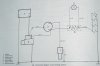
Check that a terminal (possibly numbered '50') goes live in key position 2
A stout wire from that terminal of the IGN switch should go to your insulated plate, through the coil, then to Plug number 4 at the back of the engine.

Two small wires should go from (one from each end of) the coil to the Glow warning lamp.

In your case are you saying there is NO BALLAST RESISTOR?

If that is so, then your series glowplugs may have been exposed to 12 volts every start-up, and I don't think they can stand that for long. One of them has probably burned out - OPEN circuit.

Test them. Take one wire off each plug before testing.
Each plug must show continuity low ohms resistance.
If the plug shows infinite resistance it's burned out, and NONE of them will heat up.

CharlesY
 
Many thanks for all this. Will get to it as soon as I can - ie in a couple of days. May I get back to you once I can see what the score is?
Chapgrill
 
Many thanks for all this. Will get to it as soon as I can - ie in a couple of days. May I get back to you once I can see what the score is?
Chapgrill


Sure, we all want to know how this pans out, and I now feel pretty sure than my diesel vehicles bible is wrong as regards its wiring diagrams for the 2.25 engines.

You can PM me if you like.

CharlesY
 
I have found this excellent thread, which shows the wiring for the 2 types of glow plugs and goes on to show how to wire in newer type using a relay.

Land Rover UK Forums

I have the issue of mine was fitted with the later type but they did not work as in the engine will not fire. I was then giving the earlier type by my local motor factor, now after reading the above thread I realise that I do not have the insulators so I can't wire in the new earlier type glow plugs which I now have.
 
Well just spent a couple of hours making the wires to hook up the hair pin type glow plugs (the new ones I bought) I had to use some rubber hose cut into 15mm lengths to act as insulator between the positive and negative on each plug, but using a test lamp they all work when joined together. Now tomorrows job transfer that working circuit to the engine hook it up to the ballast resistor and start the engine. Easy Peasy I'm sure.
 
I've found (thanks to CharlesY) that on my Series III the plugs are connected in parallel (as opposed to series as indicated by the wiring diagram) - parallel plugs having just one terminal and earthing to the block, while series plugs have 2 terminals. ??Sounds like you are switching from parallel to series-type plugs?
In my case Haynes and the LR handbook are wrong in showing series wiring on the plugs - which has caused/is causing some headaches re the ballast resistor etc given that mine are wired in parallel.
Chapgrill

If he is switching TO series plugs he will have to fit the ballast resistor in series with the cable to the first plug, though in fact it wouldn't matter where it was fitted as long as it was before the final earth connection. Up on the engine bay bulkhead is best as the thing could get quite warm after a while.

If you send full voltage to series plugs, instead of each plug getting about 1.7 volts (less than 2v) each one will get about 3 volts, nearly double. You could be sure they will heat up VERY bloody hot, but my guess would be one of them would burn out first time in 20 seconds or less, and then none of them would work.


CharlesY
 
Well just spent a couple of hours making the wires to hook up the hair pin type glow plugs (the new ones I bought) I had to use some rubber hose cut into 15mm lengths to act as insulator between the positive and negative on each plug, but using a test lamp they all work when joined together. Now tomorrows job transfer that working circuit to the engine hook it up to the ballast resistor and start the engine. Easy Peasy I'm sure.

Don't worry about the different looking plugs.
There are two types:
SHEATHED - a smooth bodied plug all the way with the heated bit inside.
EXPOSED - the hot wire is clearly sticking out the end, sometimes coiled.

Exposed works well but burns out sooner in the fierce combustion conditions, though with recent low sulphur fuels becoming more common they should last longer.

CharlesY
 
Unlike CharlesY I'm lucky the resistor is still in place, not sure if it is working but i will find out when i put the plugs back in.

Set your meter to OHMS and measure across the coil.
It should read a fraction of an ohm. Perhaps 0.3 maybe?
However, ANY reading is good, because the resistor coil is either GOOD, or it is buggered. There won't be anything in between unless there's a bad contact somewhere.

CharlesY
 
Set your meter to OHMS and measure across the coil.
It should read a fraction of an ohm. Perhaps 0.3 maybe?
However, ANY reading is good, because the resistor coil is either GOOD, or it is buggered. There won't be anything in between unless there's a bad contact somewhere.

CharlesY

Here's a photo of the wiring diagram as shown in my big book.
From the PMs it looks like you are OK! Just the wee bulb is wrong voltage.

CharlesY
 

Attachments

  • GlowWire.jpg
    GlowWire.jpg
    69.1 KB · Views: 1,907
Here's a photo of the wiring diagram as shown in my big book.
From the PMs it looks like you are OK! Just the wee bulb is wrong voltage.

CharlesY

LOOKING AT THAT WIRING DIAGRAM SUGGESTS THAT THE "GLOW" POSITION IS ALSO THE "STARTER" POSITION, THUS GLOW ONLY TAKES PLACE AS THE STARTER IS ENGAGED.

Does anyone have a Series manual for this age of car?

I just find it hard to believe they would wire it that way, but, it makes it like a petrol engine to start (If it starts that is) and the IGN switch would be the same a petrol one.

Then again, it's a LandRover, so one could expect anything!

CharlesY
 
Back
Top