SimonBrown
Well-Known Member
- Posts
- 133
One of the joys of this kind of work is finding you need a new tool. Got some holes to countersink in a tight spot sourced an air drill from Fleabay.

Izzy has now moved into the garage and is up on axle stands. Coolant has been dumped and the rad and intercooler off.


Finding a hardspot for the axle stand took longer when the RH rear chassis rail revealed its corrosion.

This is repairable. But there are other repairs/horror shows that have settled my mind. A new galv chassis will be ordered at some point in the future.
Smaller jobs include painting some of the body brackets and intercooler mounts.

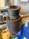
And sorting the front prop with new UJs, derust and paint...but not in that order.

Thats on the shelf ready to go back on.
Izzy has now moved into the garage and is up on axle stands. Coolant has been dumped and the rad and intercooler off.
Finding a hardspot for the axle stand took longer when the RH rear chassis rail revealed its corrosion.
This is repairable. But there are other repairs/horror shows that have settled my mind. A new galv chassis will be ordered at some point in the future.
Smaller jobs include painting some of the body brackets and intercooler mounts.
And sorting the front prop with new UJs, derust and paint...but not in that order.
Thats on the shelf ready to go back on.