CakeBandit

Active Member
I thought I would change Alternators to a ACR type since the old one is a makeshift everything and has caused me lots of problems.

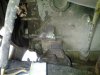
In the picture- is that one long stud threaded in or two studs one on each end?
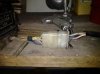
Whats the best way to remove such with out snapping both ends off?

I am trying to make way for a Series 3 Alternator bracket. I just removed the makeshift bracket (PO), and these studs must be for the old Dynamo.
The holes line up for the Series 3 bracket, but the long threaded stud on the front- needs to be a bolt coming through from the opposite end, (if that makes any sense).

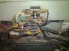
A bonus questions - The ACR type alternator has a internal voltage regulator right? One wire to Starter solenoid and one wire too a dummy light?


(Series2a 109, 2.25L Petrol)
 

Attachments

  • threads.jpg
    threads.jpg
    39.9 KB · Views: 1,816
there are 2 holes there inner is threaded outer not ,should take long bolt to hold alt bracket ,2 wires needed on from main battery lead on starter other through bulb in dash
 
The later alternators need all three wires connected, one for the power feed, one for the ignition light and one for the regulator voltage sensing. Just wire both big terminals to the solenoid with thick wire (rated to whichever ACR alternator you have) and the little terminal to the bulb in the dash, the other side of the bulb to a switched live.
 
Looking at the old wiring today, I have 3 wires left after removing the voltage regulater. 1 large wire - Starter switch, and two smaller wires, one going to a dummy light and another going to the fuse box. What should I do with the extra wire going to the fuse box?
 
If it's a brown wire then it looks like the feed to the fusebox for the horn, interior light and inspection socket, should have been connected to the B output of the regulator. Connect it to the live feed from the alternator at the solenoid.
 
Finished taking out a alternator and the external voltage regulator mounted to the fender, then put in a series 3 alternator bracket and installed a new ACR type Alternator (internal voltage regulator) with appropriate plug.

Hooked the large wire from one of the two large term at alternator to the solenoid, the sense wire to the dummy light. Then the 3rd extra (brown with white stripe) moved it to the the same terminal where I put the large wire and the other end stays the same -that goes to the fuse box. (Incidentally I did pull this wire (brown with white stripe) from the fuse box while the engine was running and the horn still worked)

So here is the deal now. Hooked up the terminals to the bat. Battery dead, so I charged it for a hour and she starts right up. While I run it for a couple hours I check the head lights , horn , signals, interior light, temp gauge, fuel gauge. Every thing seems to be o.k. so I check the voltage and I get almost 15 at the battery. I go to shut down and low and behold the ignition switch is disabled -engine still runs, so I have to shut down by pulling the lead.

When I pulled the lead and the engine stopped I did get the indicator light for the Alternator on but no ignition indicator light. (worked before- when ignition on / ignition dummy light on).

Oxides, anybody?... I am not very good with electricity. hehe
 
Do you know if it used to be positive earth? The wiring colour codes might make a bit more sense to me.
 
I am not sure. it used to have a dynmo. The PO said he put in a new genuine wire harness after the old one shorted out and melted down.
 
Yeah, I can do basic operations with one. I was thinking about following a series 3 wiring diagram tomorrow and poke around hopefully with out starting any fires. Hehe
 
OK, I think I see what's going on here. I've found a readable wiring diagram for a 2a +earth vehicle and the colour codes sound like they match your vehicle, I presume yours used to be +earth but at some stage was converted to -earth.
The wires from the regulator box are:-
terminal D, two yellow wires, one from the dynamo, now redundant, one to the charge warning light. Terminal F, yellow/green wire, from dynamo, now redundant.
Terminal A, brown/white, live feed to battery via solenoid for charging, replaced with wire from thick terminal on alternator to solenoid.
Terminal A1 brown/blue to ignition switch (terminal A?) to provide ignition switched positive feeds. Also second wire (possibly also brown blue but my diagram isn't clear) to fuse A1/A2 for interior lighting. These should be fed from the solenoid terminal.

So, what you should now have is:-

Both larger terminals via 40ish amp wires to solenoid battery terminal.
Small alternator terminal to one side of the charge light (possibly via existing yellow wire) other side of light to switched positive.
Connection from solenoid battery terminal to ignition switch A terminal to provide switched positive, possibly via existing brown/blue wire.
Connection from solenoid battery terminal to fuse A1/A2 to power interior lights (NOT fuse A3/A4 as this will bypass ignition switch).

And that should do you.
 
Thanks oxides, I think I am going to hook up the battery charger and set it on the lowest setting and not have the battery hooked up as I poke around. I see from a diagram the wires your talking about. I'll post back later about my progress.
 
Well I unpluged the wire from solennoid to the fuse box and the ignition switch is working again, no indicated light though when ignition is on and engine stopped. The lights, horn and interior light work when ignition switch is off - yea', the charge indicater light works as it did before the operation.
I attached a picture of the wire I pulled(that I also just made) to give me back control of the ignition switch.This was the wire that used to go to the voltage regulator.
You can see from the second picture where the wire used to go to the voltage regulater. A white wire with a red stripe. You can see where I cut the wire too.
 

Attachments

  • 20110731_074424.jpg
    20110731_074424.jpg
    91.5 KB · Views: 3,502
  • 1312074179491.jpg
    1312074179491.jpg
    85.4 KB · Views: 318
Hmm, there's more connections on the fusebox than I would have expected and some of the colours look a bit odd - they don't agree with the wiring diagram I've got. Still, if it's now working....
 
oxides or anybody, can you look at this diagram I uploaded. Its a diagram from a series 3, combined with a diagram from a 2a. The changes I want to make are highlighted, just want some opinion if its correct though...

I got a bunch of free-time again. +++
 

Attachments

  • Series 2a conversionb.jpg
    Series 2a conversionb.jpg
    138 KB · Views: 1,791
That looks about right but I'd run a second thick wire from the other alternator large terminal to the solenoid 'cos you might need it for the voltage sensing for the regulator.
 

Similar threads