anaalmnse

New Member
Hello
I want to help I have a Land Rover, Model 2004.110 Defender, has the electrical problem, and because of that my country is not available where the Land Rover frequently can not find who can fix it until now, the car spins the engine but does not operate, knowing that the fuel is pumped from the tank, but it was fuel injection unit does not respond, I'm you open the box ECU, and is expected to be a bummer of it but unfortunately I did not understand a thing, can I get your chart by any map painting or electrical circuit, so I can review it.
Come on things that are expected to be the cause of this crash, I hope to help because I did not I find it fixed it in libya

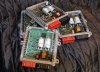
And put a picture of a private piece ecu like my car
 

Attachments

  • land rover 110 ecu.jpg
    land rover 110 ecu.jpg
    117.4 KB · Views: 3,972
:pound: sorry, but i think you will need to have a better grasp of the english language to allow us to make sense of your issue.
 
:pound: sorry, but i think you will need to have a better grasp of the english language to allow us to make sense of your issue.
Unfortunately, I use the translator

I think part of the request is "does anyone have a circuit diagram of an ECU"
Yes, it's true

I edit the speech market
I own a Land Rover , Defender Model 110 , Model Year 2004 .
You got a problem in the car.
( Explain the problem )
When you try to start the car , the engine spinning , but it does not work .
Have you checked the fuel pump , I found the pump operates , and send fuel to the engine, but I do not know whether the engine to burn fuel or not .
You are trying to examine (BOX ECU), and when you examined the device voltmeters there enter the electricity to the BOX, but there is no power out of the box.
I want advice to repair the car , there is not a qualified technician for Land Rover in Libya , because the car is available in abundance .
If the problem is in the fund ecu, does anyone have a circuit diagram of an ECU, until it is tested ? .
this number is written above the Box nnn5000020
 
Last edited:
i've tried to find an ECU intenal diagram myself without success... but how did you realise it's an ECU fault tho? ...they're quite reliable

are you sure that the crank sensor is OK?, measure voltage on the sensor output while cranking...you must get 2 - 3V AC!!! there.
 
i've tried to find an ECU intenal diagram myself without success... but how did you realise it's an ECU fault tho? Just a guess


are you sure that the crank sensor is OK?, measure voltage on the sensor output while cranking...you must get 2 - 3V AC!!! there.

Can you explain more
I do not know these things, can you give me pictures of her, and also how I can scan
 
the attachment is from a discovery Td5 but the engine and that part of the management is the same, even that ECU is used on D2-s aswell

The CKP sensor can fail the following ways or supply incorrect signal:
l Sensor assembly loose.
l Incorrect spacer fitted.
l Sensor open circuit.
l Sensor short circuit.
l Incorrect fitting and integrity of the sensor.
l Water ingress.
In the event of a CKP sensor signal failure any of the following symptoms may be observed:
l Engine cranks but fails to start.
l MIL remains on at all times.
l Engine misfires (CKP sensor incorrectly fitted).
l Engine runs roughly or even stalls (CKP sensor incorrectly fitted).
CKP does not have any backup strategy and if it fails the engine will stop running and fail to start.
 

Attachments

  • Td5 crank sensor.jpg
    Td5 crank sensor.jpg
    153.5 KB · Views: 2,006

Similar threads