Warthog110

Member
Hey there from Kenya! After benefiting from this forum for a couple of weeks in my repairs, I'm finally making my first post. We purchased a 1989 110 about a month ago, and since any vehicle that has been in Africa long has been molested by shoddy "mechanics," I'm slowly working my way through the entire electrical system. (We've had waaaaaaay too many dangerous situations in our previous vehicle from unexpected and unknown problems that chose to reach the breaking point in the middle of no where!)

So, my first questions are below. I've tried to identify by the schematics, but don't see any matching colors:
1. Can you help me identify this relay? It was located behind the steering column - I'm guessing something to do with the oil pressure check light?
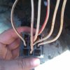
Relay x_s.jpg
Colors are: 85-White, 86-White/Brown, 87a-White x2 (one is a jumper from 85), 30-White/orange (maybe pink - it's faded), 87-White/red

2. What is this connector? Something to do with a radio? Also behind steering column. Colors are: red, brown/orange (pink?), blue/red (could be purple or pink), blue/white, white/red
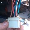
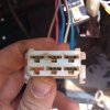
plugx1_s.jpg

plugx2_s.jpg

3. When we got the car, it had a push-button start connecting brown to the starter (white/red). There was no start relay, and the wires that should have been connected were taped up behind the passenger fuse box. I assumed this was done because the 3rd position on the ignition switch was faulty. I was able to clean it up and get it working again, then I wired up a relay and that appears to work great.
But now I appear to have a different - possibly related? - problem. There is somehow continuity between white/red and white. I have no idea how! I stripped the dash and followed from the ignition switch to the fuse box and relay, and see no signs of melting or grounding. Even when I disconnect the ignition switch, relay, starter, and fuses, they are still continuous. The only thing I can't see very well is what happens beyond the bulkhead. Any ideas what to check? From the wiring diagram, it seems like it should be nearly impossible. Has anyone ever had contact within the female side of a relay plug?
 
Last edited:
Not certain what the first relay is controlling, but from the pinout it seems that when the oil pressure is low (commonly used as an 'engine not running' signal) whatever is connected to pin 30 is powered only when the starter is active. When the oil pressure is not low, it's powered from the ignition switch. :confused:

Is the 110 petrol or diesel? If it's a petrol (with electric fuel pump) it could be that this relay is there to switch off the fuel pump unless the engine is running or starting.


The other connector is for the dim-dip relay. This was only fitted for the UK market, and switches the low beam headlights on at reduced intensity when the side lights are on and the engine's running.

There is a standard colour code for all the wires- this may be useful:Lucas wire colour codes for Land Rover
 
Last edited:
Thanks for the link. I have a British standard color codes, but invariably the mystery wire was blank on the list. The Lucas one is more complete for some of them.

Any ideas about the start and run circuits getting shorted together?
 
2. Those colours look like the dim/dip circuit and the socket might be there to connect to a voltage regulator.

3. White goes to earth via various gauges. White/Red could go to ground if something happens at any one of the brake check relay, brake fluid switch or oil pressure switch. That would provide your connection.
 
Thanks Boguing - I see a brake check relay on all the schematics, but haven't found one anywhere on the vehicle. Where is it normally located?

The only relays I've spotted are:
1. The mystery one in my first post (oil pressure instrument light at start?) - behind instrument panel
2. Voltage sensitive relay - behind instrument panel
3. I think a timer relay for the defrost/defogger circuits - behind instrument panel
- Is this a correct assumption? 30=N, 86=BP, 85=LG/W (or GW), 87=W
4. A corroded flasher relay (currently removed as I'm waiting for a replacement) - passenger side fuses
5. Horn relay (an obvious DIY job - is it even necessary on this model?) - by radiator
6. The mount for a dim-dip relay by fuses, but someone made connections instead of relay
7. Start relay was missing - I added it myself per circuit diagram

Are there any other standard relays that should be present for this year vehicle (1989)? Should I add a couple for safety?

Thanks!
 
Oh - Flying Pete - I forgot to answer you that the engine is the 2.5L petrol. So far the only white/brown wire I've seen is the one from just above the oil filter, so I think we're correct in thinking it's related to oil pressure.
 
Then again, I'm looking at another post where someone gave fuel pump cutoff relay colors as WP, WN, WR & white. In my last test (before I discovered W & WR were continuous) the fuel pump was not cutting on in the run position (position 2) on the ignition switch as it normally does. I don't see WN or even a relay on the older circuit diagrams (except for oil).

Do any of you with older petrol engines have a cutoff relay - or is it just the carb solenoid?

Fairly sure this is to do with the mystery relay (point 1 in the original post).

How this should work is that when the oil pressure is low (engine not running) the fuel pump will be off unless the key is turned to 'start'. When the engine starts (the oil pressure comes up) the relay will switch over and the fuel pump will be powered when the ignition is on.
 
A) Brake relay.

No idea where it is - my 1989 110 is a pile of bits, and the standard electrical system was one of the first things that I threw away!

I'd suggest that it is likely to be near the instrument cluster. It has White/Red (to ignition switch and starter motor) and Black/White (to warning light panel) wires and a connection to earth.

B) Mystery plug. No idea, but looking purely at wire colours:-

I can't find a White/Brown anywhere on the wiring diagram that I have.

White/Orange is used for Ig switch to radio and on to fuses (and on to heater blower).

White/Red is used twice. One from ig switch to start relay, and second from start relay to the elusive brake check relay.


Seems that there is a clue here?
 
Thanks for all your help! I followed the output from the mystery relay (white/pink or orange) through the firewall and it was part of a connector which included feed from water temp, oil pressure, alternator, plus 2 browns and the push to the starter. On the engine side of the connector, the white connection was all shriveled up and cut somewhere near the alternator. I suspect someone draped it too close to the engine and melted through the insulation and grounded to the engine block. Apparently it did some damage inside the connector - there was continuity between a few of the wires. I cut the connector off, and viola - my problem was fixed!

So now I'm curious what it was that wire supposed to connect to? I'm missing a white connection to provide positive feed to the ignition coil, and it should be the same line to the solenoids on the carburetor. Since the whole start system was jacked up, someone bypassed it all and made a splice into a green wire to go to coil and solenoids. I'd rather do it the way it was intended. Does that sound right - that the output from the mystery relay would go to the ignition coil and fuel shutoff solenoid? Since the relay doesn't exist on any diagrams I have, I can't really check.

If any of you have intact wiring (1989 Petrol) - I'd love for you to take a look and see where the positive feed to the coil comes from. If it's the same connector I had, it would share with brown/yellow, green/blue, white/brown, white/red, and two browns.

I may just try it (I don't think it could hurt) after I double check all my grounds, etc. Wish me luck!
 
Last edited:
Aaaarg! I connected everything and started it up - at least the fuel pump kicked in this time, but the starter came on in 2nd position and wouldn't kick off - again! Checked continuity on white and white/red again, and sure enough, they're shorted again. I don't get it - it was fine after I cut off the connector.

So I unplugged all the old connector stuff, the starter, the starter relay and the battery and still have continuity. I'm at a loss.
 
Does that sound right - that the output from the mystery relay would go to the ignition coil and fuel shutoff solenoid? Since the relay doesn't exist on any diagrams I have, I can't really check.

That could make sense. What it's doing in that case is turning off the supply to the ignition coil while the engine is off and the key is on. Also acts as a crude fail-safe mechanism where a loss of oil pressure will shut down the engine.

It sounds plausible that, when the connection to the ignition coil died, someone who had a vague idea what they were doing tapped into one of the existing key-switched circuits to get things working.

It's beginning to sound like it would be easier and safer to consider a full rewire. At least that way you'll know exactly which wires do what, and remove the potential for nasty surprises.
 
I'm beginning to think so! What can I say...this car's been in Africa for too many years. :frusty: We'll be swapping out the engine in a few months with a 300 Tdi, so will need to rewire a bit anyway. I know the history of the donor vehicle, and hopefully the wiring harness is in much better shape. Then I might just a new harness for the other side. OEM parts can be pretty pricey (if not downright impossible to find) so hopefully I can do it.
 
If you go for the rewire, it's worth trying to get the whole wiring harness out complete if possible. You can then use it as a guide for the lengths of the new wires and build the rewired harness outside the vehicle. Not sure of the availability of parts in Kenya, but if you can it's worth using the correct colours of wire to make later troubleshooting easier. You could either do it according to the land rover diagram, or make sensible upgrades such as extra relays for the headlights, individual circuit fuses etc.
 

Similar threads