I was chatting to a Polish chap a few years back about his code reader/diag box that he had developed for the L Series 620. He was intrigued and bought a Freelander L Series ECU that he plugged into his 620.

It sort of worked. The engine fired up and idled, but would not rev much.

Presumably differences in injection pump.
 
Thanks for the leads - have messaged SAWS.
Thanks GG - looking for a bit better than sort of works but hey, let me have the guys details - he may have developed on ! There are clearly large similarities between the Rover software and the Land Rover - just need to get all functions to work. I need a Rover 1.8 T and Freelander hybrid ECU.
He just did diag for the diesel.
 
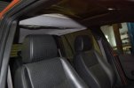
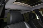
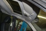
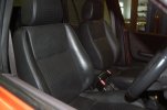
Not reported on this for a while. Have been busy, will post photos. Now has refurbed headlining, all interior removed, carpet cleaned and HSE leather fitted after clean and leather treatment. Replacement HSE steering wheel. All box sections and sills sprayed with Lanoguard.

Plan now is to fit replacement exhaust rear box as rotted. Wax and refurb underside and then use for a while.

Still thinking about engine swap. May also consider transplanting a TD4 and auto box with replacement looms and fuse box from a donor of the same age. That should be simpler ??

Looks great inside now anyway. Will think on it.
 
I still have work to do on the Rover 75 ECU in the Freelander 1. It works really well except for air conditioning and cooling fans.
I think that the air con pressure sensor actually goes to the GM6 ECU in the 75 and to the cluster in the Freelander, so I suspect that there are CANbus signals that tell the MEMS3 whether the AC is gassed or not.
I need to see if I can find these CANbus signals, but I think you know by now that if they are there I'll probably find them.
The other issue is that the 75 has a trinary switch to control the cooling fans. I need to figure out how to convert a Freelander to a 75 trinary system, but surely it can't be that difficult to do.
I would say watch my auto 1.8 thread for a few more weeks and see how I get on.
We already know that the patches that we did to my 1.8 auto ECU can also be ported to a 1.8 turbo ECU. There is actually very little difference between an auto and manual ECU on the 75, it's basically just different maps.
Right now everything that I already did would be applicable to putting a 75 turbo ECU in a manual Freelander.
 
Thanks Phillip. I did get a response from Andrew. His view was that to wire the cooling and air con to match the Rover 75 diagram would be the only sensible way forward.

I note that the Muddy 1.8T has air con disconnected and removed so they haven't cracked it yet.

Will be watching with interest. Meanwhile, will further study the Rover and F1 wiring and see what is involved in making a new loom up.
 
How about I work on the AC and you figure out how the 75 trinary switch system works? because I can't understand it.
Currently mine just runs the cooling fans on full power all the time, which Andrew says is "emergency mode" because the trinary switch system isn't there.
This seems fixable to me with a little effort.
 
Here are some photos for your gratification! Also, shows I haven't been doing nowt.

All interior removed, carpet cleaned, replaced headlining, fitted cleaned and leather treated HSE seats.
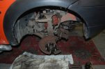
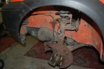
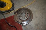
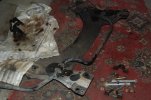
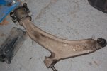
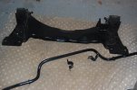
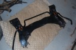
Then, started underneath. Dropped off subframe, wishbones (ball joints loose), brake discs (badly worn), drop links (rattly), ARB and bushes.

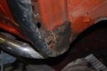
Also, my standard mod, dropped out wheel arch liners, cleaned, derusted, sprayed with Lanoguard, fitted stainless bolt spires and screws to aid removal in the future. Look at that mud - fortunately no rust behind it.
Will be cleaning and painting all components that remain.
Powder coated components and new discs etc to go on, then round to the rear.

. DSC_0209.JPGDSC_0210.JPGDSC_0211.JPGDSC_0212.JPGDSC_0213.JPGDSC_0214.JPGDSC_0215.JPGDSC_0216.JPGDSC_0217.JPGDSC_0218.JPGDSC_0219.JPGDSC_0220.JPG
 
Stripped out the rear arch covers and cleaned, Lanoguarded and refitted with stainless fixings.
Painted and fitted new brake drums.
All wheels chemically cleaned and refitted.

Will leave subframe for now. Have got a powder coated one for the rear, but need to strip suspension and replace long bolts etc. It seems ok for now. Rear silencer replaced, old one broke at the input pipe joint.

Plan is to use it with the 1.8, see how it goes. Have replaced cam seals so that it doesn't drown in oil.

Then, either a turbo or an engine conversion - TBD....

Photos tomorrow.
 
I know nothing
 

Attachments

  • IMG_0222.jpeg
    IMG_0222.jpeg
    513.7 KB · Views: 117
  • IMG_0232.jpeg
    IMG_0232.jpeg
    342.8 KB · Views: 127
  • IMG_0334.jpeg
    IMG_0334.jpeg
    332.6 KB · Views: 115
Looks a great conversion. Be interested to know more. Was it a Rover 1.8T engine or a Freelander 1.8 with 1.8T conrods? Have you used the Rover 75 ECU or does it have a seperate boost controller? Have you seen the work that @PScan is doing to try to configure cooling fans and air con? How was or is this going to be addressed? Very aware that you are a business and may want to sell solutions amd maybe not give too much detail. Is there a purchasable 1.8T package likely in the near future and if so, what does it comprise please? Your conversion is what is inspiring my thoughts so brilliant work. Any help you can give would be very much appreciated Warren.
 
I had a chat with SAWS about your "forever" project.
We see three ways to do it:-

1. Stick with the stock ECU, add an external boost controller, and remap your stock ECU to use the boost. Use pscan to calibrate the boost controller. This is a well trodden path for SAWS and they can remap your stock ECU remotely using pscan.

2. Use a Steptronic ECU and remap it to use the extra channels on this ECU to electronically control the turbo. The problem with this approach is that these ECUs are getting more and more rare, and, we guess that the hill descent/TC, and maybe all the other stuff that depends on CANbus, is going to mess up. SAWS have done this with other turbo conversions (on MG / Rovers) but I think not a Freelander.

3. Use a Rover 75 turbo ECU, but then you need the Andrew Revell adapter box to convert from PG1 crank sensor to Rover 75 ECU input, which is what I have done (but without the turbo).

4. If you want to go automatic transmission and turbo then that's basically a variation of 3.

Personally if I wanted to stay with a manual transmission I'd do number 1. It's simpler, cleaner, less expensive (because you don't need a new ECU) etc etc, but it is a matter of opinion.
 
Thanks for the input. Just out of interest, will a Rover 75 crank sensor not physically fit the Freelander engine ? Same block I thought. Would it need Rover flywheel too?
 
The Rover 75 crank sensor is fitted to the transmission bell housing. The trigger wheel is either part of the Dual Mass Flywheel or welded to the outside of the torque converter. The trigger wheel tooth pattern seems the same.
 
apparently the shape of the teeth is different for VR and Hall Effect sensors, and if you use a Hall Effect sensor (which a 75 ECU needs) it won't like the shape of the teeth that PG1 flywheel has.
 

Similar threads