Hi, everyone.
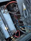
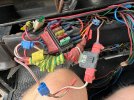
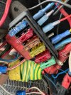
As far as I can tell a previous owner of our 110 (1986) was an avid collector of short lengths of wire in random colours, mostly red. They also had a large supply of fuses, connection blocks and insulation tape. At some point they decided to remove all the original wiring from the vehicle and replaced it with items from their collection.
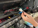
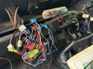
My son and I are trying to unpick their work. We’ve removed several miles of unnecessary wire from under the seats, along with several redundant fuse boxes, and have been working back towards the original fuse box. Today we started unpicking the electrical spaghetti hidden behind the dashboard. It’s bad.
Anyway — I thought this was all going well but then realised that when I start the engine the Kenlow fan isn’t running. I’ve tried adjusting the thermostat across its whole range and it doesn’t come on.
Now I am trying to work out whether a) I’ve disturbed/disconnected something that has now broken it or b) the engine isn’t getting hot enough for it to come on. Or perhaps c) there is yet another secret fuse that has blown.
is there a test that will help me figure out whether I’ve broken it? Can I force it to come on?
Would you expect a Kenlow to come on with a cold engine?
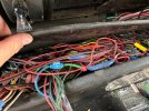
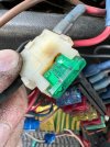
The fan wiring disappears into a scary homemade loom where most of the wires change colour every 20cm so it is a real pain trying to trace it. I’ve got a phone/network wire tone tracing kit somewhere so that may be my next step.
Thanks in advance. Pics attached for your amusement.
As far as I can tell a previous owner of our 110 (1986) was an avid collector of short lengths of wire in random colours, mostly red. They also had a large supply of fuses, connection blocks and insulation tape. At some point they decided to remove all the original wiring from the vehicle and replaced it with items from their collection.
My son and I are trying to unpick their work. We’ve removed several miles of unnecessary wire from under the seats, along with several redundant fuse boxes, and have been working back towards the original fuse box. Today we started unpicking the electrical spaghetti hidden behind the dashboard. It’s bad.
Anyway — I thought this was all going well but then realised that when I start the engine the Kenlow fan isn’t running. I’ve tried adjusting the thermostat across its whole range and it doesn’t come on.
Now I am trying to work out whether a) I’ve disturbed/disconnected something that has now broken it or b) the engine isn’t getting hot enough for it to come on. Or perhaps c) there is yet another secret fuse that has blown.
is there a test that will help me figure out whether I’ve broken it? Can I force it to come on?
Would you expect a Kenlow to come on with a cold engine?
The fan wiring disappears into a scary homemade loom where most of the wires change colour every 20cm so it is a real pain trying to trace it. I’ve got a phone/network wire tone tracing kit somewhere so that may be my next step.
Thanks in advance. Pics attached for your amusement.
Attachments
Last edited:

") ) if you turn the sensor though it’s range I would expect it to come on at 1 end, if the engine was a little warm.
) if you turn the sensor though it’s range I would expect it to come on at 1 end, if the engine was a little warm. )
) Sorry I can’t help, but best of luck!